A new 3D printing infill pattern - woven infill
- Ilhan Esmail

- Dec 21, 2024
- 2 min read
One of the biggest challenges in 3D printing today is the issue of orthogonal part properties—essentially, parts are much weaker in the Z-direction compared to the X-Y plane. Typically, Z-direction strength is about 60% of the X-Y strength, though this varies depending on the material and printing conditions. This discrepancy arises from the layer-by-layer deposition process: each layer of plastic has time to cool before the next layer is applied, leading to weaker layer adhesion.
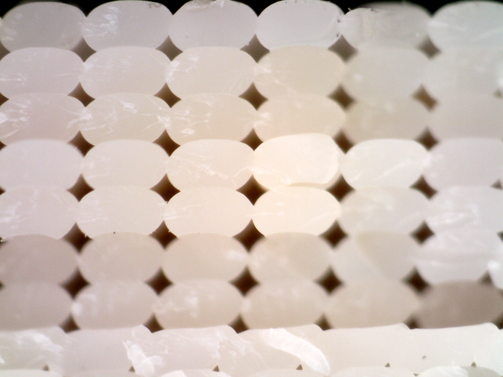
Beyond this, additional factors such as high plastic viscosity (poor flowability) or suboptimal extrusion width-to-height ratios can result in voids within the print. These voids, often diamond-shaped as seen in the microscope image below, act as nucleation sites for crack propagation, further compromising part strength.
In recent years, the 3D printing community has turned its attention to non-planar 3D printing—a technique that allows for Z-axis movements alongside X and Y movements within the same "layer." In fact, the traditional concept of layers becomes irrelevant when all three axes are working in unison, making slicing a far more complex process. One key question arises: how do you determine Z-axis movements based on part design?
To address this, I explored a straightforward approach: weaving infill patterns with intentional Z-axis variations. The idea is to prevent cracks from propagating along a single flat plane which is typically the failure mode under quasi-static tensile loading in Z. Here's a visualization of 2 layers, where an extra layer is woven between the purple and cyan tracks.

The z-gaps between the sinusoidal waves and the linear moves are half a typical layer height and the distance between the beads is 2 times the extrusion width.
Sanity check - why would we purposefully add gaps between the extrusion paths, isn't the point to fill in gaps that are generated from typical rectilinear infill patterns? Kinda. The goal is to create a denser infill patterns by compressing the extruded plastic between two adjacent extrusion lines, so a purposeful gap is fine as long as the design attempts to fill in the gap.


Comments